


Product Introduction
2. Control protocol support: Sony visca, pelco-p and PELCO-D are optional
3. The camera supports the access of various domestic cameras connected to Hikvision ds-2zmn series movement and its protocol
4. Size: 50mm * 50mm
5. Middle positioning hole: 26.4 * 40, 38 * 38, 45 * 45, aperture: 2mm
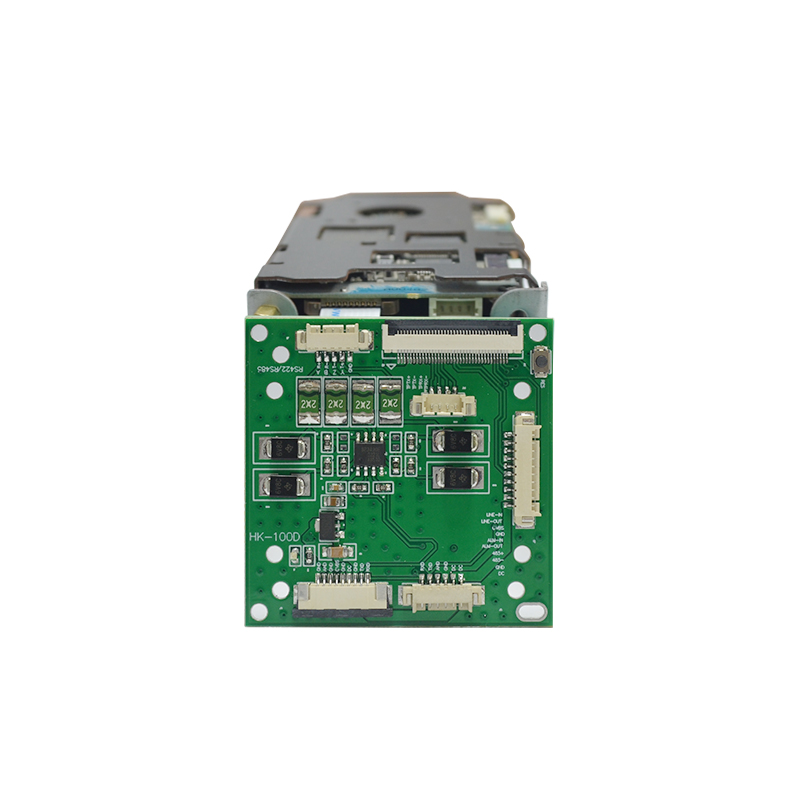
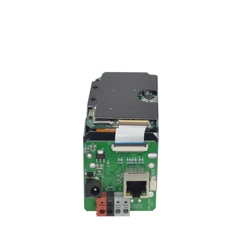
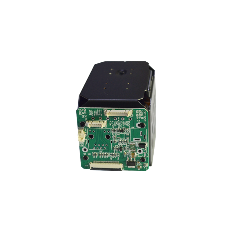
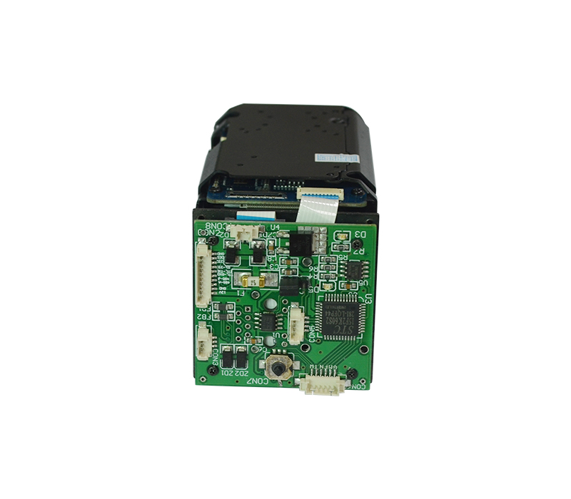
Product Parameters
|
Table 1 Interface function description table |
||
|
Serial number |
Interface name |
Description |
|
1 |
J5 6P Power input port |
There are 6 pins in total, from right to left, pins 1-9 are defined in Table 2 |
|
2 |
J4 9P output port |
9 pin corners in total, from right to left, pins 1-9 in order of definition see table 3 |
|
3 |
J3 10P output port |
There are 10 pins in total, from top to bottom, pins 1-10 are defined in Table 4 |
|
4 |
J2 36P camera interface |
36P camera interface |
|
5 |
J1 5P RS422/485 output port |
There are 5 pins in total, from left to right, pins 1-5 are defined in Table 5 |
|
6 |
J6 6P network output port |
There are 6 pins in total, from left to right, pins 1-6 are defined in Table 6 |
|
Table 2 J5 6P power input port |
||
|
Serial number |
Name of needle corner |
Description |
|
1 |
DC12V |
12V power input |
|
2 |
DC12V |
Power ground |
|
3 |
GND |
Camera serial transmission |
|
4 |
AHD |
Camera serial reception |
|
5 |
TXD |
Camera serial transmission |
|
6 |
RXD |
Camera serial reception |
|
Table 3 J4 9P output port |
||
|
Serial number |
Name of needle corner |
Description |
|
1 |
RXD |
Camera serial reception |
|
2 |
TXD |
Camera serial transmission |
|
3 |
GND |
Power ground |
|
4 |
DC |
12V power input |
|
5 |
GND |
Power ground |
|
6 |
CVBS |
CVBS signal output |
|
7 |
GND |
Power ground |
|
8 |
AHD |
AHD signals |
|
9 |
GND |
Power ground |
|
Table 4 J3 10P output port |
||
|
Serial number |
Name of needle corner |
Description |
|
1 |
LINE-IN |
Audio input |
|
2 |
LINE-OUT |
Audio output |
|
3 |
CVBS |
CVBS signal output |
|
4 |
GND |
Power ground |
|
5 |
ALM-IN |
Alarm signal input |
|
6 |
ALM-OUT |
Alarm signal output |
|
7 |
485+ |
Camera serial reception |
|
8 |
485- |
Camera serial transmission |
|
9 |
GND |
Power ground |
|
10 |
DC |
12V power input |
|
Table 5 J1 5P RS422/485 output port |
||
|
Serial number |
Name of needle corner |
Description |
|
1 |
R+ |
Receiver in-phase input |
|
2 |
R- |
Receiver inverting input |
|
3 |
T- |
Driver inverted output |
|
4 |
T+ |
Drive in-phase output |
|
5 |
GND |
Power ground |
|
Table 6 J6 Network output ports |
||
|
Serial number |
Name of needle corner |
Description |
|
1 |
TPTX+ |
Fiber optic transmission |
|
2 |
TPTX- |
Fiber optic transmission |
|
3 |
TPRX+ |
Fiber optic reception |
|
4 |
TPRX- |
Fiber optic reception |
|
5 |
LINK |
Connection status indicator |
|
6 |
ACT |
Signal transmission indicator |


 +8613798538021